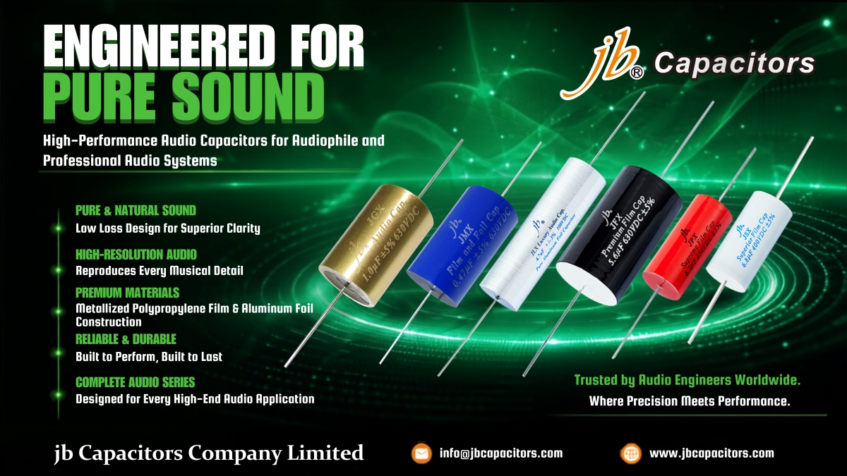
Elevate Your Audio Experience: A Deep Dive into jb Capacitors’ High-End Audio Series
In the world of high-fidelity acoustics, every passive component plays a defining role in signal integrity and tonal purity. For audiophiles, professional audio system designers, and crossover network builders, selecting the right film capacitor is not just a technical necessity—it is an art form.
jb Capacitors Company is proud to introduce our latest Audio Film Capacitors portfolio, designed specifically to deliver exceptional acoustic resolution, ultra-low distortion, and unparalleled transparency[cite: 74]. From high-end speaker crossovers to tube amplifiers, these precision-engineered axial metallized polypropylene capacitors support the global high-fidelity audio industry's most demanding requirements[cite: 75].
1. JFX – Premium Metallized Polypropylene Film Capacitors
The JFX Premium series is a highly versatile and popular choice among audio designers. Featuring a tubular axial structure with tinned pure copper leads, it offers exceptional reliability and outstanding electrical properties at an accessible price point.
- Acoustic Character: Balanced, highly analytical, natural and transparent sonic performance.
- Core Construction: Metallized Polypropylene Film with very low dissipation factor (DF).
- Applications: Speaker crossovers, vacuum tube amplifiers, audio power supplies, coupling circuits.
2. JSX – Superior Metallized Polypropylene Film Capacitors
Stepping up in sonic density, the JSX Superior series features optimized inner structures to further minimize electrical resonance and microphonic distortions.
- Acoustic Character: Extended soundstage, deeper bass texture, and smoother high-frequency transitions.
- Key Strengths: Extremely low ESR and high-purity materials for minimized signal loss.
- Applications: High-end loudspeaker systems, premium pre-amplifiers, signal processing equipment.
3. JPX – Supreme Metallized Polypropylene Film Capacitors
The JPX Supreme series represents the peak of our standard metallized film technology, utilizing advanced winding methods to guarantee incredibly tight capacitance tolerances and minimal internal parasitic inductance.
- Acoustic Character: Exceptional airiness, crystal-clear imaging, and precise instrument localization.
- Perfect For: High-end tweeters, active filters, and premium acoustic crossover designs.
4. JLX & JMX – Luxury & Music Aluminum Foil Capacitors
For pure signal purity, the JLX Luxury and JMX Music series leverage actual Aluminum Foil coupled with metallized film. These series deliver unparalleled dynamics and speed that standard metallized-only caps simply cannot match.
- Acoustic Character: Rich, emotionally engaging mid-range, thunderous yet tightly controlled bass transients.
- Distinctive Design: Solid aluminum foil layers for superior current carrying capacity and thermal stability.
5. JGX – Gold Copper Tube and Film Capacitors
The ultimate reference grade JGX Gold series features a rigid copper tube housing with special epoxy sealing. It provides maximum mechanical damping to eliminate microphonic vibrations completely.
- Acoustic Character: Liquid-smooth, organic warmth, superb micro-dynamics, and dead-silent background.
- Sought After By: Boutique tube amp builders and reference-level speaker designers.
6. Comparison of jb Premium Audio Capacitors
| Series | Type / Materials | Acoustic Highlights | Datasheet |
|---|---|---|---|
JFX Premium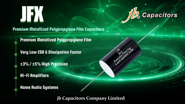
|
Metallized Polypropylene Film, Axial | Highly transparent, analytical, natural tonal balance. | 📥 PDF Specs |
JSX Superior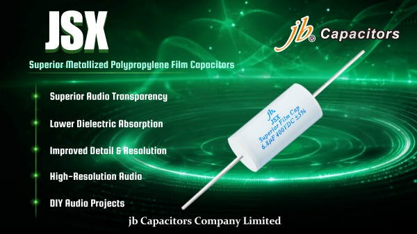
|
Metallized Polypropylene Film, Axial | Extended soundstage, enhanced bass definition and depth. | 📥 PDF Specs |
JPX Supreme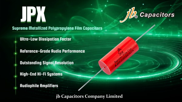
|
Metallized Polypropylene Film, Axial | Ultra-clear transient response, crisp airy highs, precise imaging. | 📥 PDF Specs |
JLX Luxury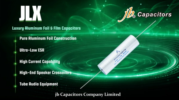
|
Aluminum Foil & Film, Axial | Incredible mid-range realism, organic warmth, rich resolution. | 📥 PDF Specs |
JMX Music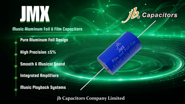
|
Aluminum Foil & Film, Axial | Dynamic punch, superb physical speed, smooth vocal performance. | 📥 PDF Specs |
JGX Gold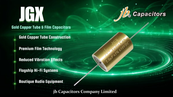
|
Gold/Copper Tube & Film, Axial | Reference standard damping, liquid-smooth highs, silent backdrop. | 📥 PDF Specs |
7. Experience the Premium jb Production Standards
At jb Capacitors, quality assurance and continuous precision are embedded at every step of our manufacturing. Our production plant employs high-precision automatic winding equipment, multi-stage temperature curing chambers, and 100% rigorous electrical verification for capacitance tolerance, dissipation factor, and insulation resistance. This uncompromising technical workflow ensures that every single capacitor delivered to acoustic labs and manufacturing facilities operates with world-class acoustic reliability.
Elevate Your Acoustic System with jb Audio Capacitors
Whether you are a boutique audio brand looking for custom performance components or an electronics distributor sourcing high-end passive devices, jb provides reliable lead times, technical support, and premium samples tailored to your project.
Recommended SEO Keywords (comma-separated)
audio capacitors, metallized polypropylene film capacitors, speaker crossover capacitors, crossover networks, axial film capacitors, jb Capacitors audio, JFX Premium, JSX Superior, JPX Supreme, Aluminum Foil capacitors, copper tube capacitors, JGX Gold, audio decoupling, high-fidelity acoustics, premium audio components, hi-fi capacitor manufacturer, audiophile film capacitors, tube amp coupling capacitor.